Table of Contents
- 1. Porosity after machining: what to check first
- 2. Narrowing the cause by position and shape
- 3. Checking the relationship between machining allowance and porosity
- 4. Process data review sequence
- Key Points
- Conclusion
- Frequently Asked Questions
Porosity after machining: the CNC cell reports small holes — for example, around 1 mm in diameter — appearing on a machined surface even though the part passed visual inspection as-cast. A common reaction on the production floor is to change casting parameters immediately — shot speed, intensification pressure. But that approach skips the diagnostic step that separates casting-related defects from machining-related exposure. The porosity generally already exists in the casting; machining determines whether and where the cavity becomes exposed. The check sequence matters more than the first parameter change.
1. Porosity after machining: what to check first
Record and classify before you change anything. Map the defect positions onto the part drawing and answer three questions:
- Is the porosity concentrated at the same location every time, or randomly distributed?
- Are the cavities round and spherical, or irregular and branched?
- Are they close to the surface or deeper under it?
Repeatable positions tend to indicate tooling-related factors: gate, overflow, venting, or flow-front convergence. Random positions should prompt checking melt quality or process variation. Defect location is a diagnostic clue, not a standalone verdict. This single classification already determines which direction you should investigate.
2. Narrowing the cause by position and shape
As a general tendency, gas porosity is round and spherical while shrinkage porosity is irregular and dendritic. Porosity exposed after machining may be found in last-filled areas, in the final solidification zones of thick sections, and on faces with large machining allowances. Defect location is an important diagnostic clue, but it should not be used alone to determine gas versus shrinkage porosity.
The following are general diagnostic tendencies. Do not identify the defect mechanism from shape alone; use defect location, section inspection, and process data together.
| Observation | Gas porosity (entrapment) | Shrinkage porosity |
|---|---|---|
| Shape | Round, spherical | Irregular, branched |
| Repeatability | Random to flow-front convergence | Final solidification area of thick sections |
| Size | Small, dispersed | Larger, localized |
| Main countermeasures | Venting, vacuum, gate velocity, melt cleanliness | Intensification, cooling, gate solidification timing |
A key engineering point: intensification pressure is effective for shrinkage porosity but has limited effect on gas porosity. For porosity dominated by entrapped gas, increasing intensification pressure may have limited corrective effect and can increase the risk of flash or die loading, depending on the actual filling, solidification and pressure-transfer conditions.
3. Checking the relationship between machining allowance and porosity
When porosity is found after machining, first confirm where the cavity was located in the as-cast part and how much of it machining exposed. Faces with larger machining allowances bring internal porosity to the surface more easily, so compare the designed allowance with the actual amount of material removed. Check the following:
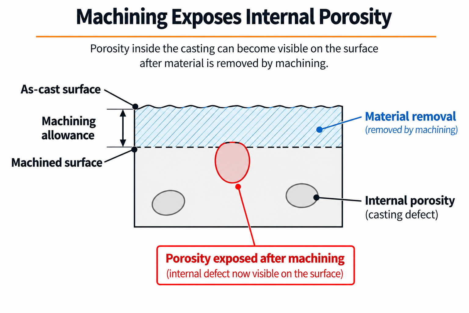
- The difference between the designed allowance and the actual material removed (machining program changes, tool wear)
- The depth distribution of the cavities — near the surface only, or continuous into the core
- If possible, compare X-ray or section results of as-cast parts with the machined condition
If the apparent defect is caused by machining position, allowance or datum conditions rather than a change in the casting itself, changing casting parameters will not address that root cause. Conversely, a recent increase in machining allowance can expose porosity that was always there — this should be treated as a machining/design change, not a casting process deterioration.
4. Process data review sequence
If position and allowance checks do not narrow the cause, review process data in this order:
- Material lot: chemistry (ADC12 standard composition per JIS H 5302), melt treatment records, recent changes — quality records should be traceable under ISO 9001 if the plant is certified
- Vacuum waveform: achieved vacuum level and timing (where vacuum is used)
- Release agent: concentration, spray pattern, lot changes
- Gate, runner and overflow condition: wear, blockage, soldering
- Shot profile: actual slow/fast transition position and gate velocity
Only after these checks should you change casting parameters, one variable at a time. Vacuum die casting is widely regarded as effective for reducing gas entrapment, but results vary with the sealing structure and achieved vacuum level — verify with waveform data rather than assumptions.
Key Points
- Diagnostic order for machining-exposed porosity: position repeatability → shape classification → machining allowance → process data
- Casting parameter changes come last. Increasing intensification for a gas defect adds risk without solving the problem
- Request defect location maps and process data from multiple lots covering the period before and after the defect increase before accepting any parameter-change proposal
Conclusion
When porosity appears after machining, the casting parameters are not the first thing to change. Verify position repeatability, defect shape, and the machining allowance first, then review material lots, vacuum waveforms, release agent, gate condition and shot profile in order. Changing parameters without identifying the cause can make the problem worse — raising intensification pressure for a gas defect is a typical example. Following this sequence helps reduce unnecessary parameter changes and makes root-cause isolation more systematic.
Related technical articles
Air porosity and leakage countermeasures · Gas porosity vs. shrinkage: how to distinguish the causes
Frequently Asked Questions
Q1. What should be checked first when porosity appears after machining?
A1. Defect position and repeatability. A consistent location tends to indicate tooling-related factors; random locations should prompt checking melt or process variation. Location is a clue, not a verdict.
Q2. How do you distinguish gas porosity from shrinkage porosity?
A2. As a general tendency, gas porosity is round while shrinkage porosity is irregular and dendritic. Use section inspection and position trends together.
Q3. What if changing casting parameters does not improve the defect?
A3. Re-evaluate the combination of machining allowance, die design (gate/overflow/venting) and melt management. Gather the data first.